Key takeaways
- Normal operating pressure should sit at 25–75% of the range; an oversized range wastes accuracy and an undersized one gets overloaded by surges.
- Compare total error, including temperature effect and stability; a 0.1% FS transmitter can drift several times that in a hot plant room.
- Two-wire 4–20 mA is the default; check loop resistance = (supply − minimum voltage) ÷ 0.02 A.
- 1/2" NPT and G 1/2 are not interchangeable; name the exact thread on the datasheet.
- Use a siphon on steam, a snubber on pulsating lines and a diaphragm seal on viscous or corrosive media.
The eight things a specification must state
Most transmitter problems on site trace back to a datasheet that left one of these open. Fill in every row before you ask for quotations, and compare offers against the same list.
| Parameter | What to decide | Typical choice in HVAC and utilities |
|---|---|---|
| Pressure reference | Gauge, absolute, sealed gauge or differential | Gauge |
| Range | Upper limit that puts normal pressure in the middle of the span | Normal pressure at 25–75% of range |
| Overpressure | Highest pressure the sensor must survive (surges, water hammer, test pressure) | Overload rating above the system hydro-test pressure |
| Accuracy | Reference accuracy plus temperature effect and long-term stability | 0.25–0.5% for monitoring; 0.1% or better for control and energy calculations |
| Output | 4–20 mA, 0–10 V, HART, Modbus RTU or BACnet | Two-wire 4–20 mA |
| Process connection | Thread type and size, or flange / sanitary clamp | 1/2" NPT or G 1/2 (BSPP) |
| Wetted materials | Diaphragm and port material compatible with the medium | SS 316 / 316L |
| Environment | Ingress protection, ambient and medium temperature, hazardous area | IP65 indoors; IP67 or IP68 outdoors or in pits |
Gauge, absolute, sealed gauge or differential
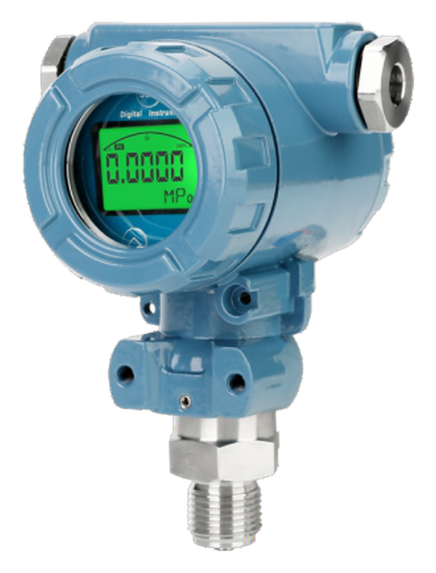
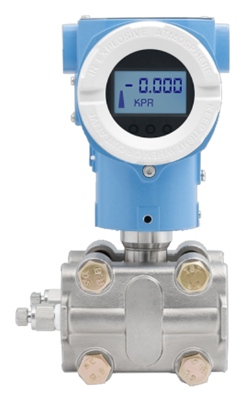
Gauge transmitters measure relative to the local atmosphere, so they read zero when the port is open to air. They suit almost all water, air, oil and hydraulic duty. Absolute transmitters measure from a perfect vacuum; use them for vacuum systems, vapour pressure and anywhere a change in barometric pressure (roughly 1 kPa with weather, and far more with altitude) would distort the reading. Sealed gauge types have a fixed reference sealed inside and are used at high ranges where a vent is undesirable. Differential transmitters measure the difference between two ports, for filters, strainers, flow elements and closed-tank level.
A gauge transmitter needs a vent to atmosphere, usually through the cable or the housing. If that vent gets blocked or flooded, the zero drifts. Submersible level transmitters therefore use vented cable, and the cable end must terminate in a dry box.
Choosing the range
A transmitter's accuracy is quoted as a percentage of its span, so an oversized range wastes accuracy. A transmitter ranged far below the system maximum, on the other hand, sees overload every time a pump starts or a valve slams. The practical rule is to put normal operating pressure in the middle half of the range and make sure the worst-case pressure stays below the overload rating.
Worked example. A chilled-water pump discharge runs at 6 bar, can reach 9 bar at shut-off head, and the system is hydro-tested at 15 bar. A 0–10 bar transmitter puts 6 bar at 60% of span and covers shut-off. Its overload rating (often two to three times span) must cover the 15 bar test, or the transmitter must be isolated during the test. A 0–25 bar transmitter would also work, but each 0.25% of span would now be 0.06 bar instead of 0.025 bar.
Smart (HART) transmitters can be re-ranged over a turndown ratio such as 10:1 or more, which helps stores standardise on fewer models. Accuracy usually worsens as the transmitter is turned down, so check the turndown accuracy formula in the datasheet.
What the accuracy figure really means
The headline number (for example ±0.1% FS) is usually reference accuracy at a stable laboratory temperature. It typically combines non-linearity, hysteresis and repeatability. On site, three other terms often matter more:
- Temperature effect: zero and span shift with ambient or medium temperature, often given per °C or per 10 °C.
- Long-term stability: drift per year, which sets the calibration interval.
- Static pressure effect (differential transmitters only): the zero shift when both ports sit at high line pressure.
Add them up before comparing offers. A transmitter rated ±0.1% FS with a temperature effect of 0.02% FS per °C, installed in a plant room that swings 30 °C from its calibration temperature, can show a temperature error of 0.6% FS, six times its headline accuracy. Some manufacturers publish a total error band over a stated temperature range; that figure is the fairer comparison.
| Duty | Sensible accuracy class |
|---|---|
| Local indication, alarm, pump protection | ±0.5% FS |
| BMS monitoring, booster-set control | ±0.25% FS |
| Process control, custody or energy calculations | ±0.1% FS or better, with stated total error band |
Output signal and wiring
4–20 mA two-wire remains the default because the same two wires carry power and signal, current is not affected by cable resistance, and the live zero lets the control system tell a real zero (4 mA) from a broken wire (0 mA). Many transmitters follow the NAMUR NE 43 convention, driving the loop to 3.6 mA or below, or 21 mA or above, to signal a fault. Configure the PLC or BMS to alarm on those values.
Check the loop budget. Maximum loop resistance = (supply voltage − transmitter minimum voltage) ÷ 0.02 A. With a 24 V DC supply and a transmitter that needs 8 V, the loop can take (24 − 8) ÷ 0.02 = 800 Ω, including the input resistor, any barrier and the cable. HART communication needs at least 250 Ω in the loop.
| Output | Strengths | Watch out for |
|---|---|---|
| 4–20 mA (two-wire) | Long cable runs, broken-wire detection, universal | Loop resistance budget |
| 4–20 mA + HART | Remote configuration and diagnostics on the same pair | Needs a HART-capable host or handheld |
| 0–10 V (three-wire) | Common on HVAC controllers | Voltage drop and noise on long runs; no broken-wire detection at 0 V |
| Modbus RTU / BACnet MS/TP | Several devices on one RS-485 bus, extra data points | Addressing, termination and integration effort |
Process connection, materials and accessories
Name the thread exactly. 1/2" NPT (a tapered thread to ASME B1.20.1) and G 1/2 (a parallel BSP thread to ISO 228-1, sealed with a bonded washer) look similar but do not seal against each other. Match the transmitter to the tapping on the pipe or to the gauge cock specified in the piping drawings.
SS 316 or 316L wetted parts suit water, glycol, air, oil and most utility service. Ceramic sensors resist abrasion and many chemicals. For seawater, chlorides, acids or high-purity duty, confirm the diaphragm material with the supplier against the actual medium.
Accessories decide the life of the transmitter:
- Isolation valve or two-valve manifold so the transmitter can be removed or zero-checked without draining the line.
- Siphon (pigtail) on steam, so a condensate seal protects the sensor from live steam temperature.
- Snubber on pulsating reciprocating-pump or hydraulic lines.
- Diaphragm seal with capillary for viscous, crystallising, corrosive, hot or sanitary media, or a flush-diaphragm transmitter on a flanged nozzle.
Mount the transmitter below the tapping on liquid lines so trapped air drains back to the pipe, and above the tapping on gas lines so condensate drains back.
Environment and hazardous areas
IP ratings follow IEC 60529: IP65 resists water jets, IP67 survives temporary immersion, and IP68 is for continuous immersion at a depth the manufacturer states, which is what submersible level transmitters need. Check the cable gland or connector as well as the housing; the rating applies only with the specified gland fitted.
In a classified hazardous area the transmitter must carry a protection concept under the IEC 60079 series, typically intrinsic safety (Ex ia or Ex ib, used with a barrier or isolator) or flameproof (Ex d). In India, equipment used in hazardous areas also requires PESO approval, so ask for the certificate with the quotation, not after delivery.
Quick selection by application
| Application | Typical choice |
|---|---|
| Chilled-water and condenser-water headers | Gauge, SS 316, 0–10 or 0–16 bar, 4–20 mA, isolation valve |
| Domestic water booster set | Gauge, 0–10 bar, 4–20 mA to the VFD controller |
| Compressed air header | Gauge, 0–16 bar, snubber if near a reciprocating compressor |
| Steam header | Gauge, siphon plus isolation valve, range above safety-valve setting |
| Hydraulic power pack | Gauge or sealed gauge, high overload, snubber |
| Open tank or sump level | Submersible hydrostatic transmitter, vented cable, IP68 |
| Vacuum line | Absolute transmitter |
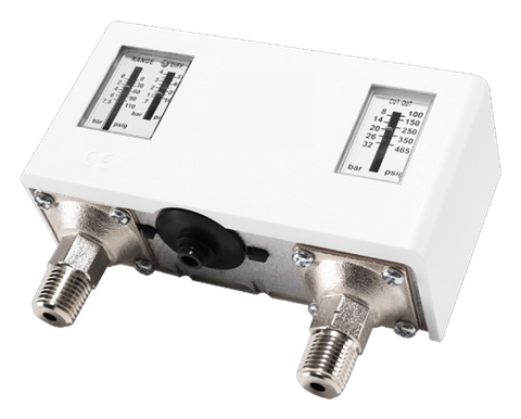
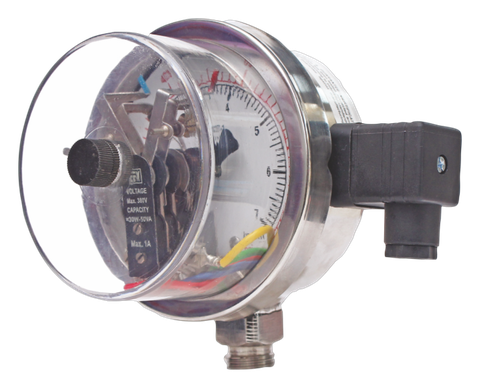
Where you need only a local reading, a pressure gauge is simpler and needs no power; where you need only an on/off contact, use a pressure switch. For filters, strainers and room pressure, see our differential pressure transmitters. Pioneer supplies gauge and absolute pressure transmitters; send your medium, normal and maximum pressure, connection and output, and our engineers will match a model.