Key takeaways
- A BTU meter is three parts working together: a flow sensor, a matched temperature sensor pair and a calculator; an error in any one shows up in the energy reading.
- EN 1434 is the European standard series for thermal energy meters and the reference most BTU meter specifications use.
- Size the flow sensor so that both design flow and minimum part-load flow sit inside its measuring range, which often means a meter smaller than the pipe.
- In chilled water the temperature difference is small, so sensor matching matters more than the absolute accuracy of either sensor.
- For tenant billing, read the meter's own cumulative energy register over M-Bus, Modbus or BACnet rather than integrating instantaneous kW in the BMS.
- A BTU meter on the plant header plus electrical energy meters gives you measured chiller plant kW/TR and exposes low delta-T problems.
What a BTU meter is
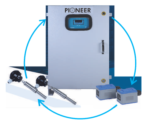
A BTU meter measures the thermal energy delivered to, or taken from, a water circuit. It has three sub-assemblies:
- Flow sensor: an electromagnetic, ultrasonic or mechanical meter in the supply or return line.
- Temperature sensor pair: two platinum resistance sensors (Pt100, Pt500 or Pt1000), one in the supply and one in the return.
- Calculator: electronics that multiply volume by temperature difference and by a heat coefficient for water at the measured temperature, then accumulate energy.
In simple terms, energy = volume × ΔT × k, where k accounts for the density and specific heat of water. A useful field check for chilled water: cooling in TR ≈ flow in m³/h × ΔT in K ÷ 3.02. For example, 60 m³/h at a 5 K difference is about 100 TR.
The name comes from the British thermal unit, but most meters register kWh, MWh or TRh. One TRh is 12,000 BTU, or about 3.517 kWh.
Where EN 1434 fits
EN 1434 is the European standard series for thermal energy (heat and cooling) meters, and the standard most BTU meter specifications reference. It treats the meter as a flow sensor, a temperature sensor pair and a calculator, and sets requirements and maximum permissible errors for each sub-assembly and for the complete meter. Flow sensors are given accuracy classes 1, 2 and 3, with class 1 the tightest.
The standard also defines the flow terms used on datasheets: qp is the permanent flow rate the meter can sustain continuously, qi the lowest flow rate at which it stays within limits, and qs the highest flow rate it can handle for short periods. It sets the temperature-pair error as a function of the temperature difference, so a meter's minimum ΔT matters as much as its flow range.
When you write a specification, ask for the accuracy class of the flow sensor, the temperature range and minimum ΔT of the calculator, and whether the meter has been tested for cooling or combined heating and cooling. A meter approved only for heating is not automatically suitable for chilled water.
Size the flow sensor by flow rate, not pipe size
Chilled-water pipework is sized for pressure drop and future load, so line-size meters often run at very low velocity. Variable primary flow and part-load operation push flow down further. Low velocity is where every flow technology loses accuracy.
Take a 100 TR tenant floor at a 5 K design ΔT: about 60 m³/h. In a 150 mm line that is roughly 0.9 m/s at design and about 0.2 m/s at a quarter of the flow. A 100 mm meter with concentric reducers sees about 2 m/s at design and 0.5 m/s at a quarter, which is comfortably inside the measuring range.
- List the design flow, the lowest expected part-load flow and any future flow.
- Choose the meter size whose range covers all three, with design flow at or below qp and minimum flow above qi.
- Check the added pressure drop of the reducers against the available pump head; it is usually small.
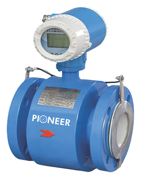
Pioneer's electromagnetic flowmeters measure 0.2 to 12 m/s in both directions at ±0.5% of measured value, from 10 to 2000 mm. For a cut-in BTU meter on chilled water this is usually the first choice: no moving parts, no pressure loss and no wear from debris.
Choosing the flow sensor technology
| Flow sensor | Strengths | Limitations | Typical use |
|---|---|---|---|
| Electromagnetic (inline) | No moving parts, short straight run, stable at low velocity | Needs a pipe cut and shutdown; needs grounding | Tenant billing, plant headers, new build |
| Ultrasonic (inline) | No moving parts, fixed calibrated geometry | Needs a pipe cut; longer straight run than a magmeter | Billing and plant meters, small to medium sizes |
| Ultrasonic (clamp-on) | No cutting or shutdown; suits large pipes | Accuracy depends on pipe data; insulation must be opened and resealed | Retrofits, plant monitoring, audits |
| Mechanical (multi-jet or Woltman) | Low cost for small sizes | Moving parts wear; strainer needed; pressure drop | Small, clean, closed circuits |
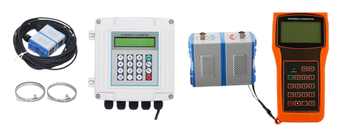
Pioneer's clamp-on ultrasonic flowmeters (1.0% of reading above 0.5 m/s, pipes from 12 mm to 4570 mm) are the practical retrofit route where a plant cannot be shut down. For billing, prefer an inline sensor; use clamp-on for monitoring or where shutdown is impossible, and verify it against a known reference after installation.
Temperature sensor pairs: why matching matters
Chilled water typically runs with a design ΔT of around 5 K, and at part load it often falls to 2 or 3 K. An error of 0.1 K between the two sensors is 2% of a 5 K difference and 5% of a 2 K difference. That is why BTU meters use a factory-matched pair, whose difference error is far smaller than the absolute tolerance of either sensor alone.
- Order the pair with the meter and keep it together; never replace one sensor of a pair.
- Do not shorten or extend the cables of 2-wire sensors. The pair is matched with its cable, and lead resistance is part of the reading. Use 4-wire sensors where the cable run to the calculator is long.
- Pt500 and Pt1000 sensors are less affected by lead resistance than Pt100.
- Install both sensors the same way: both in pockets or both direct immersion, at the same immersion depth and on similar pipe sizes.
Platinum sensor tolerance classes are defined in IEC 60751. Pioneer supplies Pt100 and Pt1000 RTD sensors; for energy metering, specify the pair as part of the meter so that it is matched and certified with the calculator.
Installation: placement and straight runs
Define the metered boundary
The supply sensor, return sensor and flow sensor must enclose exactly the load being billed. A branch, bypass or pump take-off between the sensors and the load will either be missed or billed to the wrong tenant. Put both temperature sensors at the point where the tenant's or AHU's pipework leaves the common riser.
Flow sensor position
- Many designs put the flow sensor in the return line. Whichever line you use, configure the calculator for it, because it corrects for water density at the temperature of the flow sensor.
- Place the flow sensor upstream of the two-way control valve and balancing valve, not just downstream of them.
- Give a magmeter about 5 diameters of straight pipe upstream and 2 to 3 downstream; give an ultrasonic sensor 10 diameters upstream and 5 downstream, or more after pumps and out-of-plane elbows.
- Fit isolation valves and, on critical risers, a bypass so the meter can be removed. Vent air at high points; trapped air disturbs every flow technology.
Temperature sensors
- Mount where the water is well mixed, not immediately after a tee where two streams join.
- Insulate pockets and sensor heads on chilled-water lines to stop condensation and heat gain.
- Seal sensors and the calculator after commissioning so that billing readings cannot be disturbed.
Commissioning checks
Before the load comes on, while supply and return water are at the same temperature, the two sensors should read within a small fraction of a degree of each other; a persistent offset points to a sensor or installation problem. Compare flow against the pump curve or a handheld ultrasonic flowmeter, and record the opening register readings.
Communication with the BMS
BTU meters are typically offered with one or more of the following interfaces. Confirm what your BMS and billing software can read before ordering.
- M-Bus: a wired meter-reading bus common in multi-tenant metering, read by a level converter or gateway.
- Modbus RTU over RS485: widely supported by BMS controllers and energy software.
- BACnet (MS/TP or IP): native integration into BACnet building management systems.
- Pulse outputs: energy or volume pulses for simple counters and legacy systems.
Typical points to map are cumulative energy, cumulative volume, flow rate, supply and return temperature, ΔT, instantaneous power and error or alarm status. For billing, use the meter's cumulative energy register. Integrating instantaneous kW in the BMS loses data whenever the network drops.
Tenant billing and chiller plant kW/TR
Tenant billing. Billing chilled water by measured TRh is fairer than billing by floor area, and it gives tenants a reason to save. Put one meter on each tenant or AHU branch, use the same meter type throughout the building to avoid disputes, and verify meters periodically with a portable flowmeter and reference thermometers. Pioneer's energy and water meters page covers the wider sub-metering picture, including water and electrical meters.
Plant efficiency. Chiller plant kW/TR is the total electrical input of chillers, chilled- and condenser-water pumps and cooling-tower fans, divided by the cooling delivered. Measure the cooling with a BTU meter on the chilled-water header and the power with electrical energy meters, averaged over the same intervals. ASHRAE Guideline 22 deals with instrumentation for monitoring central chilled-water plant efficiency and is a useful reference for this layout.
Header ΔT is also the best early warning of low delta-T syndrome. If the plant runs at 2 to 3 K instead of the design 5 K, it is pumping too much water and running extra chillers for the load. Plant meters need the best temperature pair you can get, because the small header ΔT magnifies any sensor error.
Decision checklist
- Is the meter for billing (inline sensor, sealed, cumulative register) or for monitoring (clamp-on acceptable)?
- What are the design flow, minimum part-load flow and future flow? Size the flow sensor to cover all three.
- Is the meter rated for cooling, and does its minimum ΔT suit your part-load conditions?
- Is the temperature pair factory-matched, with the cable length fixed?
- Do the sensor positions enclose exactly the load being billed?
- Is there enough straight run for the chosen flow technology?
- Which interface does the BMS need: M-Bus, Modbus RTU, BACnet or pulse?
- Who reads, verifies and seals the meters, and how often?
Send Pioneer the pipe sizes, design and minimum flows, supply and return temperatures, and the BMS protocol. We will recommend the meter configuration and quote, typically within 48 hours.