Key takeaways
- Vortex meters suit steam, compressed air, gases and clean low-viscosity liquids; they are a poor fit for very low flows, viscous liquids, slurries and pulsating flow.
- Size by velocity at operating conditions. Reliable measurement needs a Reynolds number of roughly 10,000 or more, so the meter is often one size below the line.
- Steam and gas meters measure actual volume; use pressure compensation (saturated steam) or pressure plus temperature compensation (superheated steam, gases) to read kg/h or Nm³/h.
- Allow typically 10–20 pipe diameters of straight run upstream (more after a control valve or two bends in different planes) and about 5 diameters downstream.
- Send minimum, normal and maximum flow, pressure, temperature and fluid data with the enquiry so the supplier can check the whole range, not just the design point.
How a vortex flowmeter works
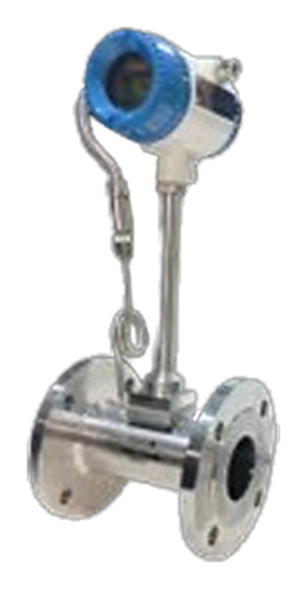
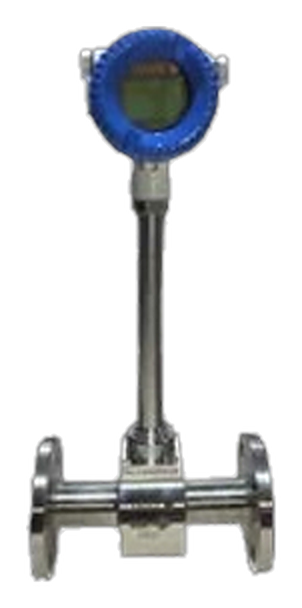
A vortex flowmeter has a bluff body (shedder bar) across the pipe. As fluid flows past it, vortices form alternately on each side and are carried downstream. This pattern is known as a von Kármán vortex street. Over the working range the shedding frequency is proportional to the flow velocity, so a sensor behind the bar counts the vortices and the transmitter converts that frequency into volumetric flow.
Because the meter has no rotating parts, there is nothing to wear out in the flow path. The same design measures liquids, gases and steam, which is why vortex meters are widely used on boiler steam headers, compressed air rings and utility gas lines in Indian process plants and commercial buildings.
Where a vortex meter fits, and where it does not
| Application | Vortex suitability | Notes |
|---|---|---|
| Saturated steam (boiler output, distribution headers) | Good | Add pressure compensation for kg/h. Wet steam reduces accuracy. |
| Superheated steam | Good | Needs pressure and temperature compensation. Check the meter's temperature rating. |
| Compressed air and nitrogen | Good | Pressure and temperature compensation gives Nm³/h for leak and consumption audits. |
| Natural gas, biogas, process gases | Good | Check gas composition, materials and hazardous-area requirements. |
| Clean water, condensate, thermal fluid | Good | For water that conducts, an electromagnetic meter is often simpler. |
| Viscous oils, slurries, fibrous liquids | Poor | Low Reynolds number or fouling of the bluff body. |
| Very low flows or large turndown | Poor | Below the minimum velocity the meter reads zero (low-flow cut-off). |
| Pulsating flow, bidirectional flow | Poor | Pulsation and reverse flow disturb vortex shedding. |
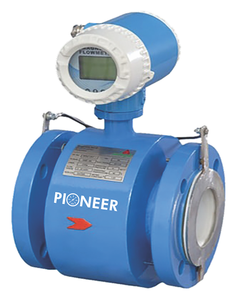
If the fluid is a conductive liquid such as chilled water, an electromagnetic flowmeter is usually the first choice. If you need true mass flow of liquids or gases with high accuracy, consider a Coriolis or thermal mass flowmeter.
Size by velocity and Reynolds number, not by pipe size
The most common vortex meter problem is oversizing. A meter chosen to match a DN100 line can sit near its low-flow cut-off for most of the day, especially on steam and gas lines that were designed for future load. Below a Reynolds number of roughly 10,000 (the exact figure depends on the design), vortex shedding becomes irregular and the meter cuts off to zero.
Typical usable velocities, which vary between manufacturers and with fluid density, are:
- Liquids: roughly 0.3–0.5 m/s minimum up to about 7–10 m/s.
- Gases and steam: a minimum of a few m/s (higher for low-density gas) up to about 60–80 m/s.
The rule is to put the normal flow in the middle of the meter's range and confirm that the minimum flow is still above the cut-off. If it is not, choose a meter one size smaller than the line with concentric reducers. The extra pressure drop is usually small, roughly two velocity heads across the meter, and it rises with the square of velocity, so check it at maximum flow.
Worked example: saturated steam at 7 bar(g)
Steam meters see volume, so start by converting mass flow to actual volume using the steam density at the operating pressure. Densities of dry saturated steam from standard steam tables:
| Pressure, bar(g) | Saturation temperature, °C | Density, kg/m³ |
|---|---|---|
| 3 | about 144 | about 2.16 |
| 5 | about 159 | about 3.17 |
| 7 | about 170 | about 4.16 |
| 10 | about 184 | about 5.64 |
For 1,000 kg/h at 7 bar(g): actual volume = 1,000 / 4.16 ≈ 240 m³/h. In Schedule 40 pipe the velocity is about 8 m/s in DN100, 14 m/s in DN80 and 31 m/s in DN50. If the boiler also runs at 250 kg/h in low-load periods, the DN100 velocity falls to about 2 m/s, which may be below the cut-off for many vortex meters. A DN80 or DN50 meter keeps the low-load velocity in the measurable range. The final choice should come from the supplier's sizing calculation with your real minimum, normal and maximum flows.
Note the saturation temperatures: a meter for 7 bar(g) steam sees about 170 °C, and a meter for 10 bar(g) sees about 184 °C. Check the process temperature rating of the meter and its electronics before you order.
Compensation: actual volume vs mass and normal flow
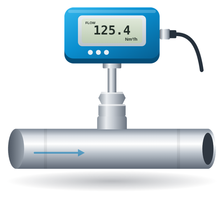
A vortex meter measures actual volumetric flow. Steam is bought and costed in kg/h and gas or compressed air in Nm³/h, so the reading must be corrected for density:
- Saturated steam: pressure and temperature are linked, so one measurement (usually pressure) is enough to calculate density.
- Superheated steam: needs both pressure and temperature.
- Compressed air and gases: needs pressure and temperature to convert actual m³/h to Nm³/h at the agreed reference conditions.
Compensation can be built into the meter (multivariable vortex meters with integral pressure and temperature sensors) or done in a flow computer, PLC or BMS using separate pressure transmitters and temperature sensors. Either way, state the reference conditions for Nm³/h in the specification. Wet steam is a separate problem: compensation assumes dry steam, so a separator and good trapping upstream improve accuracy.
Installation points that affect accuracy
Vortex meters need a well-developed, swirl-free flow profile. Typical straight-run guidance from manufacturers is:
| Upstream disturbance | Upstream straight run | Downstream |
|---|---|---|
| Concentric reducer | about 5–10D | about 5D |
| Single bend or expander | about 10–15D | about 5D |
| Two bends in different planes | about 20D or more | about 5D |
| Control valve or partly open valve | about 20–30D or more | about 5D |
Always follow the figures in the chosen meter's manual. Other practical points:
- Put control valves downstream of the meter where possible.
- Install pressure and temperature tappings downstream of the meter, at the distances the manufacturer gives, so they do not disturb the vortices.
- Avoid locations with strong pipe vibration, such as next to reciprocating compressors, or support the pipe on both sides.
- On steam lines, mount the meter so that condensate drains away, and fit a trap upstream.
- On liquid lines, keep the pipe full; vertical lines with upward flow help.
- Match the meter bore and gaskets to the pipe ID so that nothing protrudes into the flow.
What to put in the enquiry or specification
- Fluid and state (saturated steam, superheated steam, compressed air, named gas, liquid).
- Minimum, normal and maximum flow, with units (kg/h, Nm³/h or m³/h).
- Operating and design pressure and temperature.
- Line size, schedule and end connection (flange rating).
- Required output: actual volume, mass or normal volume, and whether compensation is in the meter or in the BMS/PLC.
- Signals and communication (4–20 mA, pulse, RS 485/Modbus, HART).
- Area classification, if the gas is flammable.
- Accuracy expected and how it will be verified.
With this data the supplier can check the meter over the full range, not just at the design flow. For compressed air audits, see also compressed air flowmeters, and for other technologies read electromagnetic vs ultrasonic flow meters.