Key takeaways
- Match the probe to the substrate: magnetic induction (Fe) for coatings on steel and iron, eddy current (NFe) for non-conductive coatings on non-ferrous metals.
- Zero on uncoated substrate of the same material, shape and surface profile, and verify with foils that bracket the expected thickness.
- Blast-cleaned steel makes readings look higher than the true film over the peaks, which is why ISO 19840 uses roughness correction values.
- A specification is only meaningful with a sampling rule: ISO 19840 (80-20 rule) or SSPC-PA 2 (spot averages and the 80%/120% band).
- For hot-dip galvanized cable trays and steelwork, ISO 1461 sets minimum local and mean zinc thickness by steel thickness.
What a DFT gauge measures
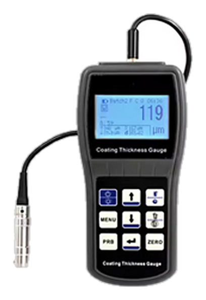
A dry film thickness (DFT) gauge, also called a coating thickness gauge or paint meter, measures the thickness of a cured coating without damaging it. Results are given in micrometres (µm) in India and Europe, or in mils in US specifications (1 mil = 25.4 µm). Typical jobs are checking primer and topcoat on structural steel, powder coating on panels and cable trays, zinc on hot-dip galvanized or pre-galvanised steel, and anodising on aluminium.
Coating thickness matters both ways. Too thin and the coating fails early by rusting or chalking; too thick and paint can crack, sag, or fail to cure properly, and you have paid for material you did not need. That is why paint specifications state a nominal DFT (and often a maximum), and why inspectors measure it before accepting a job.
Magnetic induction vs eddy current vs ultrasonic
The substrate decides the measuring principle, not the coating.
| Principle | Substrate | Coatings measured | Standard |
|---|---|---|---|
| Magnetic induction (Fe / F probe) | Steel and iron (ferromagnetic) | Paint, powder coat, zinc (galvanizing), chrome, plastic linings | ISO 2178, ASTM D7091 |
| Eddy current (NFe / N probe) | Aluminium, copper, brass, austenitic stainless steel | Paint, powder coat, anodising, other non-conductive films | ISO 2360, ASTM D7091 |
| Combined Fe/NFe | Either; the gauge detects the substrate | As above | ISO 2178 and ISO 2360 |
| Magnetic pull-off (mechanical) | Steel | Paint, zinc | ISO 2178 (pull-off type) |
| Ultrasonic | Concrete, wood, plastic, composites | Paint and coatings on non-metals; some gauges resolve individual layers | ASTM D6132 |
For most fabrication shops, paint contractors' inspectors and buyers checking steel structures or cable trays, a digital magnetic induction gauge is the everyday tool. If the same inspector also checks aluminium cladding, louvres or stainless steel enclosures, a combined Fe/NFe gauge avoids carrying two instruments. Mechanical pull-off gauges are inexpensive and need no battery, but they are slower, operator-dependent and less suited to formal records.
Specifications to check before you buy
- Range: paint systems on steel usually sit between about 50 and 500 µm; thick linings and some galvanizing on heavy sections go higher. Choose a range that covers your maximum with margin.
- Accuracy and resolution: stated as ± a few µm plus a percentage of reading. Compare at the thickness you actually measure, not at zero.
- Probe type: integral probes suit general work; separate cabled probes reach inside channels, ladder rungs and pipes. Small-tip or right-angle probes help on edges and small parts.
- Minimum substrate thickness and curvature: thin sheet, small radii and edges change readings. Check the gauge's stated limits against your thinnest sheet and smallest radius.
- Data: memory, batch statistics (mean, min, max, standard deviation), and USB or Bluetooth export make inspection reports far easier. Built-in ISO 19840 or SSPC-PA 2 modes are useful if your clients specify them.
- Calibration certificate: ask for a traceable certificate with the gauge and for certified verification foils.
How to take readings that stand up to inspection
- Zero the gauge on uncoated substrate of the same metal, thickness, shape and surface profile as the job. Zeroing on a smooth test plate and then measuring blasted steel adds an error.
- Verify with certified plastic foils (shims) or coated reference standards. A two-point adjustment with foils above and below the expected DFT gives the best accuracy across the range.
- Measure with the probe held square and steady, away from edges, holes and welds unless the specification asks for them.
- Record readings in groups as the specification requires, and note gauge serial number, verification results, and the area measured.
Surface profile: on abrasive-blasted steel the probe sits on the peaks while paint fills the valleys, so the gauge reads differently from what it would on smooth steel. ISO 19840 handles this with correction values based on the profile grade; SSPC-PA 2 handles it by adjusting the gauge on the blasted, uncoated surface. Follow whichever your project specifies.
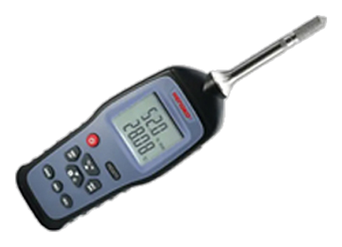
Before painting, inspectors also check surface temperature, air temperature and relative humidity: the common rule is that steel should be at least 3 °C above the dew point before coating. A handheld temperature and humidity meter with dew-point calculation does this job.
Acceptance rules: ISO 19840 and SSPC-PA 2
A nominal DFT on its own does not tell you how many readings to take or how low a single reading may go. The two common rules are:
| ISO 19840 (protective paint on rough surfaces) | SSPC-PA 2 (US practice) | |
|---|---|---|
| Basic unit | Individual readings | Spot = average of at least 3 readings close together |
| Number of measurements | By inspection area, e.g. 5 readings up to 1 m², 20 readings for 10–30 m², 30 readings for 30–100 m², then 10 more per extra 100 m² | For general areas, 5 spots per 100 ft² (about 9.3 m²), more on large or complex structures |
| Lower limit | Mean at least the nominal DFT; no reading below 80% of nominal; readings between 80% and 100% of nominal less than 20% of the total (the 80-20 rule) | Each spot not below 80% of the specified minimum; the average within the specified range |
| Upper limit | No reading above the specified maximum, where one is given | Each spot not above 120% of the specified maximum (default level) |
Agree the rule, the inspection areas and the treatment of edges and welds before work starts; most disputes about DFT are really disputes about sampling.
Checking galvanizing on cable trays and steelwork
Zinc is not magnetic, so a magnetic induction gauge measures galvanizing on steel in the same way as paint. For hot-dip galvanized articles that are not centrifuged, ISO 1461 sets minimum thickness by steel thickness (IS 4759 is the related Indian standard for structural steel):
| Steel thickness | Minimum local thickness | Minimum mean thickness |
|---|---|---|
| Above 6 mm | 70 µm | 85 µm |
| Above 3 mm up to 6 mm | 55 µm | 70 µm |
| 1.5 mm up to 3 mm | 45 µm | 55 µm |
| Below 1.5 mm | 35 µm | 45 µm |
Pre-galvanised (continuous-galvanised) sheet is specified differently: by total coating mass on both sides in g/m², for example Z275 = 275 g/m² total. As a rule of thumb, 1 µm of zinc weighs about 7 g/m², so Z275 is roughly 19–20 µm per side. This is why hot-dip galvanizing after fabrication is chosen for outdoor and corrosive areas, while pre-galvanised trays suit dry indoor areas. When you receive cable trays, a few DFT readings per piece against the specified standard are a quick receiving check.