Key takeaways
- A Pt100 RTD is the default below about 600 °C when accuracy and stability matter; thermocouples take over above that and in very harsh or fast duties.
- IEC 60751 class B allows ±(0.3 + 0.005|t|) °C and class A ±(0.15 + 0.002|t|) °C, so a class A Pt100 is about ±0.35 °C at 100 °C.
- Use 3-wire RTD connections as standard and 4-wire for the best accuracy; 2-wire Pt100 is only acceptable with very short leads or a head transmitter.
- Type K suits general duty up to about 1,200 °C, type N is more stable at high temperature, type T suits low temperatures, and R, S and B suit the hottest duties.
- The thermowell, not the sensor type, usually dominates response time, so choose its bore, wall thickness and immersion length with care.
- A head transmitter with 4–20 mA output removes lead-wire and extension-cable errors and can report a broken sensor.
How each sensor works
An RTD (resistance temperature detector) is a platinum element whose resistance rises with temperature in a known, nearly linear way. A Pt100 reads 100 Ω at 0 °C and about 138.5 Ω at 100 °C, a change of roughly 0.39 Ω per °C. A Pt1000 has ten times the resistance and ten times the change. The measuring instrument passes a small current through the element and reads the voltage.
A thermocouple is two dissimilar metal wires joined at the measuring (hot) end. It generates a small voltage, a few tens of microvolts per °C, that depends on the temperature difference between the hot junction and the cold junction where the wires reach the instrument. The instrument measures the cold-junction temperature and corrects for it, which is called cold-junction compensation. This means the extension cable must be of the matching thermocouple type, because ordinary copper cable would form a new junction.
Pt100 accuracy classes under IEC 60751
IEC 60751 defines the Pt100 resistance-temperature relationship and tolerance classes for the element. The tolerance grows with temperature (|t| is the temperature in °C, ignoring sign):
| Class | Tolerance | At 0 °C | At 100 °C |
|---|---|---|---|
| AA | ±(0.1 + 0.0017|t|) °C | ±0.10 °C | ±0.27 °C |
| A | ±(0.15 + 0.002|t|) °C | ±0.15 °C | ±0.35 °C |
| B | ±(0.3 + 0.005|t|) °C | ±0.30 °C | ±0.80 °C |
| C | ±(0.6 + 0.01|t|) °C | ±0.60 °C | ±1.60 °C |
Each class applies only over a temperature range that depends on whether the element is wire-wound or thin-film, and the tighter classes have narrower ranges. Check the sensor datasheet for the range that goes with the class you specify.
- Class B is the general industrial and HVAC default.
- Class A or AA suits energy metering, laboratories and GMP-critical points.
- Thin-film elements are compact and handle vibration well. Wire-wound elements cover wider ranges and suit the tightest classes.
The element class is only part of the total error. Lead wires, the transmitter, immersion and self-heating all add to it. Keep the measuring current low, typically around 1 mA for a Pt100, to limit self-heating.
2-wire, 3-wire and 4-wire connections
Lead-wire resistance adds directly to the RTD reading. A Pt100 changes by only about 0.39 Ω per °C, so a little lead resistance makes a large error.
- 2-wire: both leads are in the measurement. For example, 20 m of 0.5 mm² copper each way is about 1.4 Ω in total, which a Pt100 reads as roughly 3.5 °C too high, and the error changes with ambient temperature. Use 2-wire only with very short leads, with a Pt1000 (where the same lead resistance causes a tenth of the error), or with a transmitter mounted in the sensor head.
- 3-wire: the instrument measures one lead and subtracts it, assuming both current-carrying leads are equal. This is the industrial standard, provided all three cores are the same size and length and the terminations are clean.
- 4-wire: two leads carry the current and two sense the voltage, so lead resistance drops out. Use it for class A or AA sensors, calibration work and energy metering.
The sensor, cable and input card must all agree. A 4-wire sensor connected to a 3-wire input works as 3-wire; a 3-wire sensor cannot become 4-wire.
Thermocouple types and ranges under IEC 60584-1
IEC 60584-1 defines the voltage-temperature tables and tolerance classes for the standard thermocouple types. The ranges below are typical working ranges; the usable maximum also depends on wire size, sheath and atmosphere.
| Type | Conductors | Typical range | Notes |
|---|---|---|---|
| K | Nickel-chromium / nickel-aluminium | About −200 °C to 1,200 °C | General purpose and the most widely used. Can drift with time at high temperature and in reducing atmospheres. |
| J | Iron / copper-nickel | About −40 °C to 750 °C | Good in reducing atmospheres; the iron leg oxidises at higher temperatures. Common on plastics machinery. |
| T | Copper / copper-nickel | About −200 °C to 350 °C | Best base-metal type for low and sub-zero temperatures. |
| E | Nickel-chromium / copper-nickel | About −200 °C to 900 °C | Highest output per degree of the standard types. |
| N | Nicrosil / nisil | About −200 °C to 1,200 °C | More stable than K at high temperature; a good K replacement for furnaces. |
| R and S | Platinum-rhodium / platinum | About 0 °C to 1,600 °C | Noble metal: accurate and stable but costly. Needs ceramic protection. |
| B | Platinum-30% rhodium / platinum-6% rhodium | About 600 °C to 1,700 °C | For the hottest duties. Output is very small below a few hundred °C. |
Tolerances are wider than for RTDs. For type K, class 2 allows ±2.5 °C or ±0.75% of the reading, whichever is greater, and class 1 allows ±1.5 °C or ±0.4%. On top of this come cold-junction and extension-cable errors.
Response time
A bare thermocouple junction can be very fast because it has little mass, and a grounded junction (welded to the sheath tip) is faster than an insulated one. In practice the assembly decides the speed, not the sensor type.
- Sheath diameter: a 3 mm mineral-insulated sheath responds much faster than a 6 or 8 mm one.
- Thermowell: a heavy-walled well, especially with an air gap between the insert and the bore, can make the assembly much slower than the bare sensor. Specify a close-fitting insert, and a spring-loaded insert that touches the bottom of the well.
- Medium and velocity: the assembly responds faster in moving liquid than in still air or slow gas.
For fast duties such as exhaust gas, small-bore pipework or control loops with short time constants, a small-diameter grounded thermocouple or a slim RTD with a stepped or tapered well is the usual answer.
Thermowells
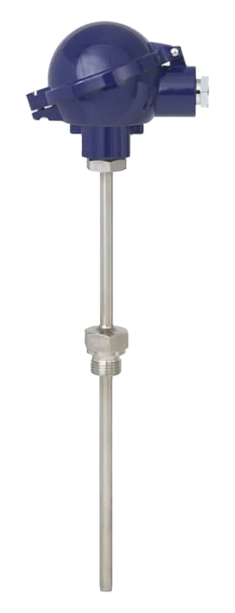
A thermowell protects the sensor from pressure, flow, corrosion and abrasion, and lets you remove the insert without draining the line.
- Material: SS 316 is the general choice. Use higher alloys or lined wells for aggressive chemicals, and ceramic protection tubes for furnaces above the limit of metal sheaths.
- Construction: wells drilled from bar stock are stronger than fabricated ones. Use flanged wells for higher pressures and corrosive duties, threaded wells for utilities, and sanitary connections for food and pharmaceutical lines.
- Immersion: the sensing element must sit fully in the flowing medium, clear of the wall. A common rule of thumb is immersion of at least ten times the well's outside diameter in liquids, and more in gases. Place the tip in the central part of the pipe.
- Vortex shedding: in fast flow, a long, slender well can vibrate and fail by fatigue. For steam, gas and high-velocity liquids, have the well checked with a wake-frequency calculation to ASME PTC 19.3 TW.
- Small pipes: install the well in an elbow, on the pipe axis facing the flow, or locally enlarge the pipe, rather than fitting a short, shallow well.
Head transmitters: 4–20 mA and HART
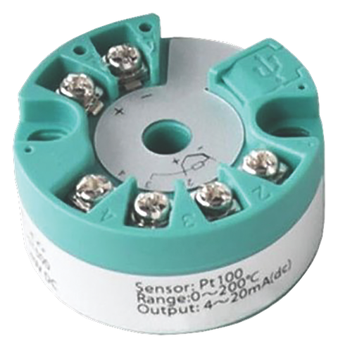
A head transmitter fits inside the sensor's connection head, or on a rail nearby, and converts the RTD or thermocouple signal into a 4–20 mA loop. This solves most wiring problems at once:
- The RTD lead-wire error disappears, and a 2-wire Pt100 with a head transmitter is acceptable.
- No long thermocouple extension cable is needed, and the transmitter compensates for the cold junction itself.
- The transmitter linearises the output, and you can set the range in it, for example 0–150 °C.
- A 4–20 mA signal resists electrical noise far better than millivolts or ohms over long runs.
- Sensor-break detection drives the output to an upscale or downscale failure level, commonly the levels set out in NAMUR NE 43, so a broken sensor is not mistaken for a real temperature.
- HART adds digital diagnostics and remote configuration over the same two wires. It is worth specifying on process plants with asset-management systems, but is usually unnecessary in building HVAC.
Pioneer supplies temperature transmitters for RTD and thermocouple inputs with 4–20 mA output (HART on some models), including a duct-mounted Pt1000 transmitter with a 200 mm SS 316 stem for HVAC.
Comparison table
| Criterion | Pt100 RTD | Thermocouple |
|---|---|---|
| Typical range | About −200 °C to 600 °C | About −200 °C to 1,700 °C depending on type |
| Element accuracy | Class A ±0.35 °C at 100 °C (IEC 60751) | Type K class 1 ±1.5 °C or ±0.4% (IEC 60584-1) |
| Long-term stability | Excellent | Good; base-metal types drift at high temperature |
| Linearity | Nearly linear | Non-linear; needs linearisation |
| Wiring | Copper cable, 3- or 4-wire | Matching extension or compensating cable, observe polarity |
| Response | Good | Can be faster, especially grounded junctions |
| Vibration and shock | Good with thin-film elements | Very good |
| Sensor cost | Higher | Lower for base-metal types; noble-metal types cost more |
| Typical uses | HVAC water and air, energy metering, process liquids, pharma, food | Furnaces, kilns, flue and exhaust gas, molten metal, plastics machinery |
When to choose which
Choose an RTD when:
- The temperature stays within about −200 °C to 600 °C.
- Accuracy and repeatability matter, for example in chilled water, heat and energy metering, sterilisation or process control within a degree.
- Long-term stability matters more than first cost.
- Heat meters need matched sensor pairs; for these, EN 1434 covers paired platinum sensors, as used with energy meters.
Choose a thermocouple when:
- The temperature is above about 600 °C.
- The sensor must be very small or very fast, or withstand heavy vibration and shock.
- Many points must be measured at low cost, for example multipoint profiles in furnaces and reactors.
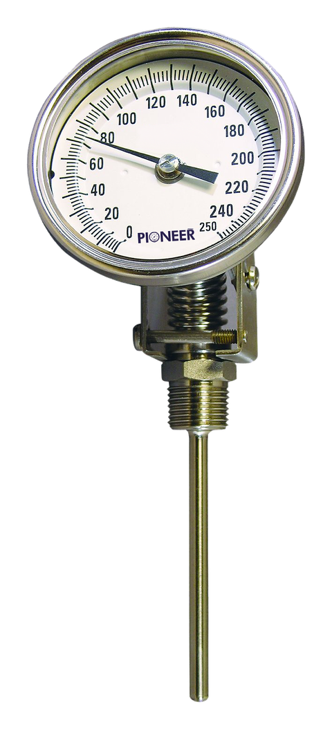
Use a dial thermometer as well where operators need local indication without power. Pioneer's dial temperature gauges come in 100–250 mm dials, ranges up to 600 °C, ±1% FSD as per EN 13190, and SS 316 stems with immersion length adjustable up to 300 mm.
Specification checklist
- Medium, normal and maximum temperature, and process pressure
- Sensor: Pt100 or Pt1000 and class (for example Pt100 class A, 3-wire), or thermocouple type and class (for example type K class 1)
- Single or duplex element
- Insert sheath diameter and construction (mineral-insulated, spring-loaded)
- Thermowell material, construction, process connection and immersion length, with wake-frequency check where needed
- Connection head and ingress protection
- Head transmitter: input, range, 4–20 mA, HART if needed, and sensor-break behaviour
- Cable type: copper for RTDs; matching extension or compensating cable for thermocouples
- Calibration certificate requirements
Pioneer supplies RTDs and thermocouples (Pt100, Pt1000 and types K, J, T, E, N, R, S and B) with transmitters and gauges. Send this checklist with your enquiry for a quotation, typically within 48 hours.